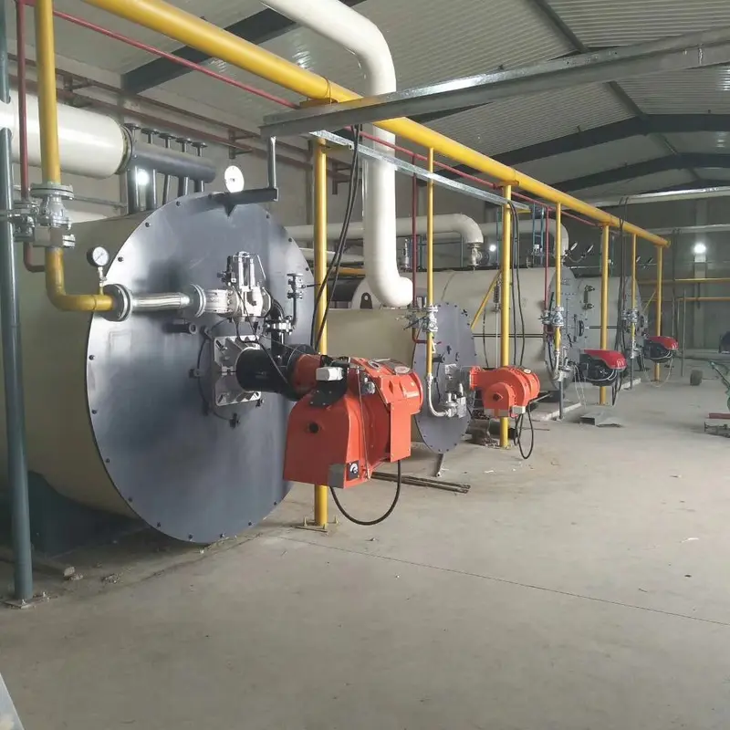
Selecting a thermal oil heater is not a sizing exercise — sizing gives you one number, and selection is the eight decisions that surround it. Four of those decisions are cast in steel the moment the purchase order is signed: maximum temperature, fuel, capacity, and coil design. Only two are genuinely fixable later without scrapping anything — the burner package and the controls. Spend your engineering time accordingly.
This guide covers the full decision set for gas, oil, coal, biomass, waste heat and electric heaters from 100 kW to 28 MW. For the arithmetic behind the kW figure itself, see how to calculate thermal oil heater capacity; this article assumes you already have a number and asks what kind of machine you should be buying.
The eight decisions, ranked by how much it costs to get wrong
| # | Decision | Sets | Fixable in the field? |
|---|---|---|---|
| 1 | Maximum operating temperature | Oil grade, coil material, film temperature limit | No — new coil |
| 2 | Fuel | Burner, furnace volume, stack, storage, permits | No — new unit |
| 3 | Capacity and turndown | Coil surface area, burner size | No — new coil |
| 4 | Coil design and heat flux | Tube velocity, pass arrangement, coking margin | No — new coil |
| 5 | Loop type (vented or blanketed) | Expansion tank, oil life, oxidation rate | Partly |
| 6 | Design pressure | Tube wall thickness, pump head, safety valve | No |
| 7 | Burner package | Modulation, NOx class, efficiency | Yes |
| 8 | Controls and instrumentation | Data, remote access, interlock logic | Yes |
The pattern is worth internalising: everything inside the pressure boundary is permanent, and everything bolted to the outside is not. Buyers routinely agonise over the choice of PLC brand — the cheapest decision on the list — while accepting a 300°C design for a 330°C process, which is the most expensive.
Decision 1 — Maximum operating temperature
This is the choice that constrains all the others, and it is where most specification errors begin.
Three temperatures matter, and they are not the same number:
- Bulk temperature — what the temperature gauge in the outlet line reads.
- Film temperature — the temperature of the oil in the thin layer touching the tube wall. Typically 20–30 K above bulk, and much higher if flow is low.
- Tube wall temperature — hotter still, because heat must cross the wall and the scale layer before it reaches the oil.
Heat transfer oils are rated by maximum bulk temperature and separately by maximum film temperature. Exceed the film limit and the fluid cracks into carbon on the tube wall — a deposit that insulates the tube, raises the wall temperature further, and accelerates the process. Once coking starts, output falls and the only cure is replacing the coil.
| Temperature band | Typical applications | Practical notes |
|---|---|---|
| 150–200°C | Food frying, textile drying, asphalt storage | Mineral oils, vented loop, simplest design |
| 200–250°C | Chemical reaction, hot presses, plywood, bitumen | Mineral oils; watch start-up viscosity |
| 250–300°C | Asphalt mixing, resin and rubber, dryers | Upper end of common mineral oils; insulation quality matters |
| 300–340°C | Chemical distillation, carbon processing | Synthetic fluids; blanketed loop worth the cost |
| Above 350°C | Special high-temperature processes | Evaluate molten salt or direct firing — oil is at its limit |
Practically: specify the maximum temperature your process could conceivably reach, not today's setpoint, and then buy one band above it. A heater specified at 300°C for a 280°C duty is being run at its design limit every day; the same machine specified at 320°C has margin for a process change and for the film temperature rise that comes with fouling.
Decision 2 — Fuel
This decision is usually made for you by the site, and pretending otherwise leads to unhappy projects. Efficiency tables matter far less than whether the gas main is reliable in February, whether you can get a permit for a coal yard, and whether anyone wants to run an ash handling shift.
| Fuel | Efficiency (LHV) | Fuel cost per GJ | Footprint and handling | Choose when |
|---|---|---|---|---|
| Natural gas | 88–92%, up to 94% with air preheater | Baseline | Compact, no storage | Pipeline available and reliable |
| LPG / light oil | 86–90% | ~1.5–2.5× gas | Tank farm, deliveries | No pipeline; remote sites |
| Heavy fuel oil | 85–88% | ~1.2–1.6× gas | Preheating, atomisation, tank heating | Cheaper residual available |
| Coal / biomass | 80–86% | ~0.3–0.6× gas | Yard, ash, dust control, taller stack | Fuel cost dominates; agro-residue nearby |
| Waste heat | Not applicable | Effective fuel ~zero | Ducting from existing source | A hot gas stream is already being vented |
| Electric | 96–99% | ~3–4× gas | Smallest, no flue, no stack | Precision, cleanliness, no emissions permit |
Fuel cost ratios move with region and season — recalculate them with your own contract prices and your actual annual GJ before committing. Two honest observations from projects that went both ways: plants that chose coal for cost reasons usually underestimated ash handling labour, and plants that chose gas for simplicity usually underestimated the cost of a new service connection and the standing charge.
For a fuel-by-fuel comparison including waste heat recovery, see gas and oil fired heaters, coal and biomass fired heaters, waste heat thermal oil heaters and electric heated thermal oil heaters.
Decision 3 — Capacity and turndown
Capacity comes from the sizing calculation; turndown is the selection decision that sits on top of it. They are independent, and buyers conflate them constantly.
Turndown is the ratio of maximum to minimum stable firing. Its importance depends entirely on your load profile:
| Load profile | Minimum turndown | Why |
|---|---|---|
| Continuous, steady process | 3:1 | Load barely moves; cycling is not an issue |
| One or two shifts with idle periods | 4:1 | Avoids constant start-stop when the line is down |
| Batch plant with several reactors on different cycles | 5:1 or better | Load swings by 60% within an hour |
| Highly variable or seasonal | Consider electric | Thyristor control gives very wide, smooth turndown |
A burner that cannot modulate down far enough will cycle: fire, reach setpoint, stop, purge, wait, fire again. Each cycle throws away purge air, adds thermal stress to the coil and produces a NOx spike at light-off. Twenty cycles an hour is not a control strategy.
The same logic makes oversizing actively harmful. A 4 MW heater carrying a 1 MW average load runs at 25% and cycles continuously, while a 2.5 MW unit in the same duty modulates smoothly and burns less fuel per delivered GJ.
Decision 4 — Coil design and heat flux
Inside the pressure boundary, two numbers decide whether the coil survives ten years or cokes in three: heat flux and oil velocity.
- Radiant heat flux — the heat crossing each square metre of tube surface in the radiant section. Organic fluids are far less forgiving than water here; designs are normally held below roughly 30 kW/m², and lower where the fluid is near its temperature limit.
- Oil velocity — flow through the tubes must stay high enough to scrub heat off the wall. Below roughly 1.5 m/s at minimum flow, the film temperature climbs sharply and coking begins. Most designs target 2–3 m/s.
This is where a cheap coil is cheap: fewer, longer passes and a smaller tube diameter save material while quietly reducing velocity at low load. The failure appears two or three seasons later as falling outlet temperature at full firing.
Ask for the velocity at minimum flow, not design flow. Many quotations state the design-point velocity, where the number always looks healthy.
Material choice follows the temperature and the fuel: carbon steel for clean service to about 300°C, alloy or stainless where temperatures or sulphur content are higher, plus a corrosion allowance that reflects the fuel's sulphur level. Coal and heavy oil service need more allowance than gas.
Decision 5 — Open vented or closed loop
| Vented (atmospheric tank) | Closed (nitrogen blanketed) | |
|---|---|---|
| Cost | Baseline | +10–20% on the loop package |
| Oil contact with air | Continuous | Excluded |
| Oxidation and acid build-up | Steady; TAN rises over years | Minimal |
| Typical fluid life at 300°C | 2–4 years | 5–8 years |
| Extra equipment | Vent, catch pot | Sealed tank, N2 supply, regulator |
| Choose when | ≤300°C, budget-led, intermittent | >300°C, continuous duty, long fluid life |
Fluid life figures are indicative and depend heavily on operating temperature and deaeration quality — but the direction is reliable. If your annual fluid charge is significant, the closed loop often pays back within one or two fluid changes.
Whichever you pick, the expansion tank must sit at the highest point of the loop with a valveless expansion line sized to 25–30% of loop volume. This is a piping rule rather than a selection choice, but it is routinely got wrong and it destroys pumps.
Decision 6 — Design pressure and hydraulics
Design pressure follows from the loop, not from the burner output. Three things set it: the static head to the expansion tank, the pump's discharge pressure, and the pressure needed to suppress vaporisation of light ends at operating temperature.
Most industrial loops land between 0.6 and 1.0 MPa, which sets tube wall thickness, flange rating and safety valve setting. Specify it once and consistently — a mismatch between the heater's design pressure and the loop's safety valve setting is a commissioning stoppage, and a safety valve that discharges hot oil vapour to a floor drain is a hazard.
Circulation is a selection decision too, and the circulation pump should be bought against the same flow and head figures as the coil, not as a separate afterthought. A pump sized for the heater's nominal flow but not checked at minimum flow is how low-velocity coking happens.
Decision 7 — Efficiency and emissions
Efficiency claims need three qualifications before they mean anything:
- LHV or HHV? The same heater is roughly 6–11 points better-looking on LHV. Ask which, and convert before comparing.
- Does it include the air preheater or economiser? A 92% figure with an air preheater and an 88% figure without are different machines at different prices.
- At what load? Efficiency falls at low firing. A number quoted at 100% load tells you nothing about a plant that runs at 40%.
Emissions are usually a permit question rather than a technical one. Low-NOx gas burners achieve roughly 50 mg/Nm³ and ultra-low-NOx designs around 30 mg/Nm³, referenced to 3% O₂ — always check the reference oxygen, because the same burner reports very different numbers at different references. If your site is in a designated air quality zone, confirm the limit before you choose the burner, not after.
Decision 8 — Skid-mounted or field-erected
The final decision with real cost attached is the boundary of supply. A skid-mounted heater arrives pre-piped and pre-wired, typically up to about 2,000 kW, and goes into service in days rather than weeks. Above roughly 5,000 kW, field erection with local piping, insulation and refractory is normal.
The trap is the interface gap: heater from one supplier, pump from another, expansion tank from a third, and nobody responsible for how they behave together. Prefer a single boundary of supply that includes the coil, burner, pump, expansion tank, controls and stack — or, if the plant splits the packages, specify exactly who owns each interface and who commissions it.
The specification sheet to send out
Give every prospective supplier the same filled-in page. It makes quotations comparable and it reveals which suppliers actually read it.
| Item | Your input |
|---|---|
| Fluid and maximum bulk temperature | e.g. mineral oil, 300°C |
| Capacity required at that temperature | kW, plus kcal/h if you use it |
| Fuel and supply pressure / calorific value | e.g. natural gas, 2 bar, 36 MJ/Nm³ |
| Design pressure | MPa |
| Allowable ΔT across the heater | K |
| Minimum flow through the coil | m³/h |
| Load profile and required turndown | e.g. batch, 5:1 |
| Venting arrangement | vented or N₂ blanketed |
| Ambient conditions and altitude | °C min/max, m above sea level |
| Emissions limit and reference O₂ | mg/Nm³ at 3% O₂ |
| Electrical supply and control voltage | V / Hz / phase |
| Site altitude derating for the burner | % |
That last row matters more than it looks: burner output falls with altitude and with lower calorific value fuel, and a coil that is correctly sized can still be matched to a burner that is short of air.
How to evaluate the suppliers
Ask these ten questions. The answers separate engineering companies from trading companies faster than any factory visit.
- What is the usable capacity at my outlet temperature, and can I see the capacity curve?
- What is the radiant heat flux in kW/m²?
- What is the oil velocity through the coil at minimum flow?
- What is the film temperature at full load and at 50% load?
- What turndown does the burner achieve, and how many starts per hour at my load profile?
- Is the quoted efficiency on LHV or HHV, and does it include the air preheater?
- What tube material and corrosion allowance, given my fuel's sulphur content?
- Which hydro test and NDT standard is actually applied, and will I get the reports?
- Who commissions the unit, and what is in the handover documentation?
- Give me two references at my temperature and my fuel, with contact details.
Red flags. No capacity curve. An efficiency figure with no LHV/HHV statement. A price that does not move between a 300°C and a 350°C design, which means both were quoted off the same template. A warranty expressed only in years rather than in fired hours. And a delivery promise materially shorter than every other bid — in this equipment category that usually means the engineering was not done.
Total cost of ownership
Capex is the smallest number in the decision and gets the most attention. Over a fifteen-year life, the split on a gas-fired unit typically looks like this:
| Cost element | Share of lifetime cost |
|---|---|
| Fuel | 70–85% |
| Capital | 8–15% |
| Maintenance, spares, fluid changes | 5–10% |
| Downtime and lost production | 2–8% |
Two points follow. First, a 3-point efficiency difference between two bids is worth more than a 10% capex difference within a couple of years — run the numbers on your annual GJ before choosing on price. Second, the downtime line is small on average and enormous in any single year it happens, which is why the coil velocity and film temperature questions in the list above matter more than they appear to.
Six selection mistakes worth avoiding
- Buying on kW price. The cheapest coil is cheap because it has less surface, thinner tube or fewer passes — you pay the difference in fuel and in coking.
- Specifying to today's setpoint. A 300°C design run at 310°C has no film temperature margin left; specify one band higher.
- Confusing capacity with turndown. A correctly sized heater with a 2:1 burner cycles all day on a batch load.
- Ignoring minimum flow. Velocity at design flow is healthy; velocity at minimum flow is what cokes the coil.
- Splitting the package too finely. Three suppliers means interfaces nobody owns and a commissioning argument.
- Comparing efficiency without the LHV/HHV and load caveats. It is the single easiest number to make look good.
Where to go next
- Chemical industry solutions — multi-reactor loops, high temperature, batch diversity
- Textile and dyeing solutions — steady medium-temperature duty, tight control
- Food processing solutions — 150–250°C, hygienic and vented arrangements
- Asphalt industry solutions — high-temperature continuous duty with heavy fuel options
- Thermal oil heater vs steam boiler — if you have not yet decided which medium to use
If you send us the specification sheet above with your own figures, the selection and the quotation come back together — including the capacity curve at your operating temperature, which is the number most of this article is really about.
Key takeaways
- Eight decisions define the machine; only the burner and controls are fixable later. Everything inside the pressure boundary is permanent.
- Maximum operating temperature is the master decision — it fixes the oil, the coil material, the film temperature limit and the loop type. Specify one band above your current setpoint.
- Fuel choice is usually made by the site, not by efficiency. Compare cost per delivered GJ at your local prices; efficiency ratios are secondary.
- Match turndown to load profile, not to the datasheet. Batch plants need 5:1 or better; oversizing causes cycling and costs fuel.
- Ask for velocity at minimum flow and film temperature at 50% load. These two numbers predict whether the coil lasts.
- On lifetime cost, fuel is 70–85% and capex is 8–15%. A three-point efficiency difference beats a 10% price difference.