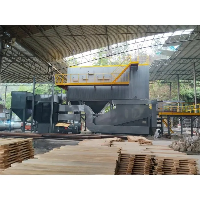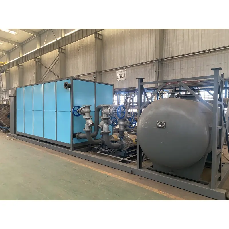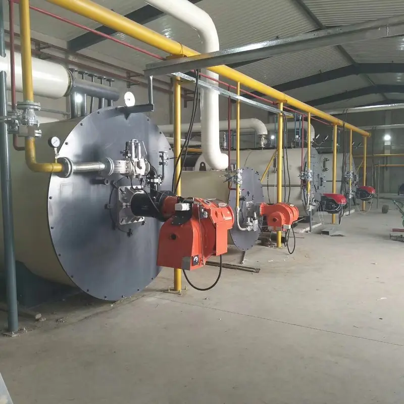
A thermal oil heater burns fuel — or uses electric elements — to heat a coil filled with organic heat transfer fluid, then pumps that fluid around a closed loop to deliver heat to the process. The fluid never boils and never leaves the loop: it gets hotter, gives up heat at the consumer, and returns to be reheated. That single design decision is what lets a thermal oil system reach 350°C while the loop itself sits close to atmospheric pressure.
The loop in five steps
- Combustion. The burner fires into a refractory-lined combustion chamber. Gas, diesel, heavy oil or dual-fuel burners are all used, with a turndown ratio of 2:1 to 10:1 depending on the burner grade.
- Heat absorption. Flue gas turns and passes over the coil two or three times — a three-pass design — before leaving through the stack. An economizer can recover the last 5–8% of that heat, which is how gas-fired units reach ≥92% thermal efficiency.
- Circulation. A centrifugal pump pushes oil through the coil at 1.5–2.5 m/s. The velocity is not incidental: slow-moving oil in a hot tube develops a stagnant boundary layer that cracks and forms carbon, so every credible design maintains turbulent flow at the worst-case load.
- Heat delivery. The oil enters the consumer's heat exchanger — reactor jacket, dryer, calender rolls, asphalt tank coil, hot press platens — and gives up 15–30 K of temperature.
- Return and deaeration. Cooled oil returns to the pump suction. The expansion tank absorbs the volume change (heat transfer oils expand roughly 0.07–0.1% per kelvin, so a 250 K rise adds about 20% to the loop volume), vents moisture and light ends, and keeps positive head on the pump.
What each component does
| Component | Function | Typical specification |
|---|---|---|
| Burner | Supplies heat input, modulates to load | Gas / oil / biomass / dual-fuel, 2:1–10:1 turndown |
| Coil | Transfers heat to the fluid | Seamless steel tube, three-pass, design heat flux below 25–30 kW/m² |
| Heater body | Contains combustion, insulates | Refractory lining plus mineral-wool lagging, cladded shell |
| Circulation pump | Drives the loop | 0.6–1.6 MPa head, high-temperature mechanical seal or water-cooled bearing |
| Expansion tank | Absorbs thermal expansion, vents air | Sized at 25–30% of total loop volume; nitrogen blanketing on high-temperature systems |
| Deaerator / separator | Removes moisture and light ends | Installed at the highest point, ahead of the expansion tank |
| Filter | Traps carbon particles and debris | 40–60 mesh, with a bypass for servicing |
| Control panel | Manages firing, interlocks, alarms | PLC with dual outlet sensors and burner management system |
| Safety devices | Prevent over-temperature and dry circulation | Safety valve, high-temperature cut-out, low-flow interlock, high flue-gas temperature trip |
Why the fluid never boils
This is the whole point of the technology, and it is easiest to see side by side.
| Working fluid | Temperature | Pressure required |
|---|---|---|
| Water / steam | 184°C | ≈1.0 MPa (10 bar) |
| Water / steam | 300°C | ≈8.6 MPa (86 bar) |
| Water / steam | 350°C | ≈16.5 MPa (165 bar) |
| Organic heat transfer fluid | 300°C | a few kPa — effectively atmospheric |
| Organic heat transfer fluid | 350°C | still below 0.1 MPa |
A pressure vessel holding 165 bar is a regulated object: inspection intervals, licensed operators, insurance loadings and a failure mode measured in fragments. A thermal oil loop at the same temperature is a pump-pressurised pipe network whose worst-case leak drips. For pure heating duties — as opposed to processes that consume steam — that trade is almost always worth making.
The five numbers that define a working design
| Parameter | Typical value | Why it matters |
|---|---|---|
| Outlet temperature | 250–350°C (special fluids to 400°C) | Sets fluid choice and tube material |
| Temperature drop across the heater | 15–30 K | Determines flow rate for a given duty |
| Tube velocity | 1.5–2.5 m/s | Below this, coking starts on the hot wall |
| Film temperature margin | 20–30 K above bulk | Governs fluid service life |
| Thermal efficiency | ≥92% gas/oil, ≥86% biomass/coal, ≥98% electric | Directly sets fuel bill |
Coil design versus fire-tube design
Both exist, and the difference shows up in operation rather than in a brochure.
| Factor | Three-pass coil | Fire-tube (smoke tube) |
|---|---|---|
| Fluid inventory | Small — fast response, less oil to buy | Large — slower response, higher fill cost |
| Footprint | Compact, vertical or horizontal | Bulkier for the same duty |
| Efficiency | Higher (tighter gas path, easier economizer integration) | Slightly lower |
| Sensitivity to flow loss | High — needs reliable interlocks | Lower — more thermal inertia |
| Fireside cleaning | Requires access doors and periodic decoking | Tubes accessible for mechanical cleaning |
Coil units dominate the 100 kW – 28 MW industrial range because the efficiency and footprint advantages outweigh the interlock discipline they demand.
What a cold start actually looks like
- Cold oil is viscous. At ambient temperature many fluids run at hundreds of centistokes; the pump may need a warm-up pass or a low-speed start until viscosity drops.
- Hold at 120–150°C. Moisture and light ends are driven off through the expansion tank. Skipping this hold is the classic route to pump cavitation two hours later.
- Ramp 20–50 K per hour. Refractory and steel expand at different rates; a fast ramp cracks linings and distorts flanges.
- Watch three readings. Pump differential pressure, expansion tank level and outlet temperature. If the level climbs steadily, the loop is still degassing.
Safety interlocks that matter more than the brochure
- Low flow / pump failure — trips the burner within seconds.
- Dual over-temperature sensors on the outlet, one of them independent of the control loop.
- Expansion tank level — low level means the loop is losing fluid or entraining air.
- High flue-gas temperature — an early warning of fouled heat transfer surfaces.
- Flame failure supervision with a post-purge cycle, non-negotiable on any code-compliant installation.
Four misconceptions worth clearing up
- "Thermal oil boiler" is a misnomer. Nothing boils. The term survives because the equipment occupies the same role as a boiler in the plant.
- The oil is not consumed like fuel. It is a closed-loop working fluid. Consumption is limited to top-up after leaks and the periodic full replacement.
- No water treatment does not mean no maintenance. Fluid sampling every 6–12 months replaces daily water chemistry — a lower-frequency duty, not an absent one.
- Hotter is not automatically better. Pushing bulk temperature toward the fluid's limit shortens its life; the useful ceiling is set by film temperature, not the setpoint on the panel.
Matching the principle to your process
If your process needs sustained heat above 150°C and does not consume steam, the loop above is the right architecture. The choice then moves to fuel:
- Gas and oil fired thermal oil heater — 100–28,000 kW, ≥92% efficiency, natural gas / LPG / diesel / heavy oil
- Coal and biomass fired thermal oil heater — ≥86% efficiency, burns wood chips, rice husk, straw, bagasse
- Electric thermal oil heater — ≥98% efficiency, zero local emissions, 10–6,000 kW
- Waste heat thermal oil heater — recovers flue-gas heat with no burner at all
Industry-specific configurations are covered on the chemical industry and textile dyeing solution pages.
Key takeaways
- A thermal oil heater is a closed liquid loop, not a boiler: burner → coil → circulating pump → consumer → return.
- The fluid stays liquid up to 350°C because its vapour pressure remains near atmospheric — that is what removes the pressure-vessel burden.
- Flow velocity and film temperature, not the outlet setpoint, decide how long the fluid lasts.
- Design values cluster tightly across the industry: 1.5–2.5 m/s velocity, 15–30 K drop, heat flux below 25–30 kW/m², expansion tank at 25–30% of loop volume.
- Efficiency is ≥92% for gas/oil, ≥86% for biomass/coal, ≥98% for electric — and it compounds over a decade of fuel bills.